
 |
 |
 |
| |
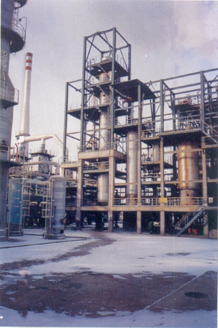
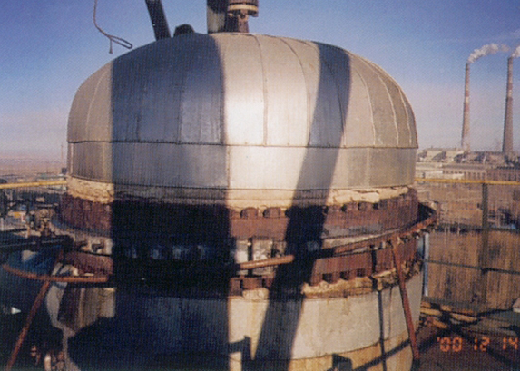
Project Case
|
|||||||||||||||||||||
Parameter of leakage medium |
Pressure |
Temperature |
Explosion limit V% |
|
Lower limit |
Upper limit |
|||
Reforming hydrogen |
1.6 |
500 |
3.84 |
68.44 |
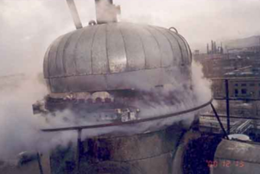
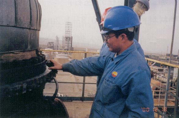
II. Capping operation
1. Preparation for operation
(1) Making and checking of operation project
(2) Field measurement
External diameter of the leakage flange
Upper flange ¢ 1880mm , ¢ 1873mm , gh; lower flange ¢ 1874mm ;
Gap between joints of flange: max 15mm , and min 12mm ;
Flange
Distance from the flange edge to the bolt: 15mm ;
Thickness of flange: 109mm (upper), 114mm (lower);
Amount and specification of bolt: M36×3×325, totally 64 pieces
(3) Design of clamp
Measuring the thickness of clamp with the strength
Internal diameter of clamp: 1880mm (upper), 1874mm (lower);
Dimension of boss: width 11mm , depth 10mm ;
Set-up and form of injector hole: 48 M 20, 8 M 14 injector through hole;
Capacity of seal cavity: roughly estimating the use level of sealant according to the capacity of seal cavity;
Installation of clamp should use the tool that does not generate spark.
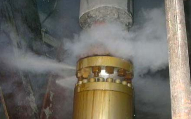
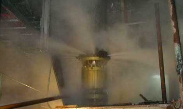
Steam protection
Protection of workers: wearing the anti-static union suit;
Adopting the anti-block preparation to prevent the plug agglomeration
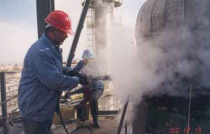
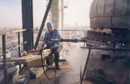
2. Injecting the sealant
(1) Injecting from the interspace of the clamp part and then to the two ends;
(2) Making full use of the characteristics of the sealant, and paying attention to the propulsion
speed and the solidification time;
(3) Filling and compacting through pressing and transferring
Controlling the propulsion speed of injectant
TXY-16# glue should be injected into the connection of clamps
VI. Explanation
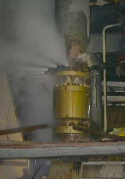
• The flange on the head becomes elliptical slightly, which influences the anastomosis of clamps
and should be compensated by soft weigh metal plate.
• Temperature of the system is 500 ℃ (the actual temperature of clamp is below 400 ℃ ). The
pressure is 1.6Mpa. The capping effect is satisfactory. The clamp could not touch hydrogen. Simple
carbon steel could be utilized as materials.
Project Case
Features of leakage parts and countermeasures against such leakage
1) Leakage parts and the conditions
① Leakage parts: DN 150mm flange, at the entrance to the emergency feed pump for boiler
Conditions of the leakage parts:
2) Conditions after the clamp was installed
3) Conditions after capping
Parameter of leakage medium
Name of leakage medium |
System pressure/MPa |
System temperature/ 0C |
Project features |
Hot water |
22 |
150 |
Cecum formed after capping 150 ℃ ---->normal temperature |
Capping processing method
1. Jig form: Strengthening the protruding flange jig through the ring cavity
Selection of sealant
Leakage conditions
In accordance with the system pressure, choosing TXY-18#
Operation temperature
Capping method:
1. Establishing the edge obstruction through the drain heat preservation
2. Controlling the injection time in line with the solidification characteristics of sealant
Capping operation procedure
1. Assembling the injection valve for each jig injection hole, and installing jig;
2. Injecting sealant into the edge ring cavity under the circumstances of drainage of the injection valve of the main sealed cavity
3. Injecting till fully compacted in line with the stipulated method, and complementing the injection after the sealant is completely solidified.
7. After establishing the edge obstruction, injecting sealant into the middle sealed cavity.
Establishing new sealed specific pressure
Injecting from the distant main leakage part sequentially, and gradually drawing close to the main drainage point
1. Boosting the resistance by force of the initial injection
(1) Pushing the resistance of friction
(2) Resistance generated from the leaked medium
2. Regional filling conditions
(1) The initial injection moves towards both sides of the injection hole;
(2) Continuing injection till the sealant gets together to the inside of the cavity;
(3) Increasing the friction till a compact entirety is formed inside the region
(4) At the edge of the region, it is a natural advance layer
3. Injecting into the sealed cavity sequentially till pressure changes
4. Establishing an effective sealed specific pressure
(1) Eventually injecting pressure, equivalent to the system pressure, into the sealed cavity;
(2) Slowly exerting pressure, and passing it till the elastic energy is accumulated and the leakage is restrained
(3) Increasing pressure, complementing it sequentially, and keeping the structure equally and closely